■홈페이지 : https://github.com/mirkix/BBBMINI
■구매처 : http://www.shenzhen2u.com/BBBMINI.html
■비글본그린에 구현 : https://www.hackster.io/mirkix/flying-beaglebone-green-448b60
Software
How to prepare your BeagleBone to use as BBBmini.
- Debian 8.6 jessie
- GCC 4.9
- Kernel 4.4 PREEMPT RT
- BBBmini devicetree loaded at startup.
Prepare microSD with your Linux host computer
- Download Debian image https://rcn-ee.net/rootfs/bb.org/testing/2016-10-02/console/BBB-blank-debian-8.6-console-armhf-2016-10-02-2gb.img.xz
- Decompress image:
unxz BBB-blank-debian-8.6-console-armhf-2016-10-02-2gb.img.xz - Copy image to microSDcard (>= 2GB):
sudo dd bs=4M if=./BBB-blank-debian-8.6-console-armhf-2016-09-21-2gb.img of=/dev/sdX/dev/sdX should point to your microSD, be careful here!!! Uselsblkto figure out, which is your mircroSD. The process can take 15-30 minutes depending on the speed of your microSD card. syncand remove mircroSD
Install Debian to your BeagleBone eMMC
- Plug prepared microSD into BeagleBone
- While holding down the boot button, apply power to the board. If there is a newer Debian installed, holding down the boot button is not necessary.
- Wait some minutes until Debian is installed (all four LEDs turned on).
- Remove power.
- Remove microSD.
- Apply power again.
- Connect to the BeagleBone
ssh debian@beaglebone - Password
temppwd - Update software:
sudo apt update && sudo apt upgrade -y - Install software:
sudo apt install -y cpufrequtils g++ liblttng-ust-dev pkg-config gawk git make device-tree-compiler screen python python-dev python-lxml python-pip - Install Python library:
sudo pip install future - Set link to pkg-config:
sudo ln -s pkg-config /usr/bin/arm-linux-gnueabihf-pkg-config - Update scripts:
cd /opt/scripts && sudo git pull - Expend partition:
sudo /opt/scripts/tools/grow_partition.sh - Install RT Kernel:
sudo /opt/scripts/tools/update_kernel.sh --bone-rt-kernel --lts-4_4 - Add BBBmini DTB:
sudo sed -i 's/#dtb=$/dtb=am335x-boneblack-bbbmini.dtb/' /boot/uEnv.txt - Set clock to fixed 1GHz
sudo sed -i 's/GOVERNOR="ondemand"/GOVERNOR="performance"/g' /etc/init.d/cpufrequtils - Reboot system:
sudo reboot - Login again:
ssh debian@beaglebone - Clone overlays:
git clone https://github.com/beagleboard/bb.org-overlays - Build and install overlays:
cd ./bb.org-overlays && ./install.sh - Add ADC DTBO:
sudo sed -i 's/#cape_enable=bone_capemgr.enable_partno=/cape_enable=bone_capemgr.enable_partno=BB-ADC/g' /boot/uEnv.txt - Reboot system:
sudo reboot - Login again:
ssh debian@beaglebone - Clone ArduPilot code:
git clone https://github.com/ArduPilot/ardupilot.git - Change dir:
cd ardupilot/Tools/Linux_HAL_Essentials/pru/rangefinderpru - Install Rangefinder firmware:
sudo make install - Your BeagleBone is now ready to use.
Compile ArduPilot native on BeagleBone
cd ardupilotgit checkout Copter-3.4.4for ArduCopter orgit checkout ArduPlane-3.7.1for ArduPlane orgit checkout APMrover2-3.1.0for ArduRovergit submodule update --init --recursivealias waf="$PWD/modules/waf/waf-light"waf configure --board=bbbminiwaf(take about 1h20m)cp build/bbbmini/bin/* /home/debian/
Cross compile ArduPilot (faster) with Ubuntu computer
Get the source code:
git clone https://github.com/diydrones/ardupilot.gitcd ardupilot./Tools/scripts/install-prereqs-ubuntu.shgit checkout Copter-3.4.4for ArduCopter orgit checkout ArduPlane-3.7.1for ArduPlane orgit checkout APMrover2-3.1.0for ArduRovergit submodule update --init --recursivealias waf="$PWD/modules/waf/waf-light"waf configure --board=bbbminiwafscp build/bbbmini/bin/* debian@beaglebone:/home/debian/
Run ArduPilot
Now you can check your hardware here.
ArduCopter: sudo /home/debian/arducopter-quad (plus parameter)
ArduPlane: sudo /home/debian/arduplane (plus parameter)
ArduRover: sudo /home/debian/ardurover (plus parameter)
To connect a MAVLink groundstation with IP 192.168.178.26 add -C udp:192.168.178.26:14550
To use MAVLink via radio connected to UART4 add -C /dev/ttyO4.
If there is a GPS connected to UART5 add -B /dev/ttyO5.
Example: MAVLink groundstation with IP 192.168.178.26 on port 14550 and GPS connected to /dev/ttyO5 UART5.
sudo /home/debian/arducopter-quad -C udp:192.168.178.26:14550 -B /dev/ttyO5
Example: MAVLink groundstation via radio connected to UART4 and GPS connected to /dev/ttyO5 UART5.
sudo /home/debian/arducopter-quad -B /dev/ttyO5 -C /dev/ttyO4
Automatic start ArduPilot after boot
If ArduPilot should start automatically at boot time follow the instructions below:
- Connect to your BeagleBone via ssh with
ssh debian@beaglebone - Edit
/etc/rc.localwithsudo nano /etc/rc.local - Modify file to (use your ArduPilot file and parameter):
#!/bin/sh -e
#
# rc.local
#
# This script is executed at the end of each multiuser runlevel.
# Make sure that the script will "exit 0" on success or any other
# value on error.
#
# In order to enable or disable this script just change the execution
# bits.
#
# By default this script does nothing.

/bin/sleep 10
/home/debian/arducopter-quad -B /dev/ttyO5 -C /dev/ttyO4 > /home/debian/arducopter.log &

exit 0
- Save file:
Strg + o+ Enter - Exit nano:
Strg + x - Reboot BegaleBone with
sudo reboot
cd ardupilotgit checkout mastergit submodule update --init --recursivealias waf="$PWD/modules/waf/waf-light"waf configure --board=bbbminiwaf examples (take some time)cp build/bbbmini/examples/* /home/debian/
cd ardupilotgit checkout mastergit submodule update --init --recursivealias waf="$PWD/modules/waf/waf-light"waf configure --board=bbbminiwaf examplesscp build/bbbmini/examples/* debian@beaglebone:/home/debian/
sudo /home/debian/INS_generic
sudo /home/debian/BARO_generic
sudo /home/debian/GPS_AUTO_test -B /dev/ttyO5
sudo /home/debian/RCInput
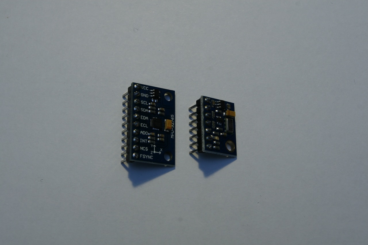
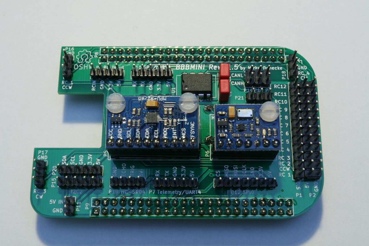
Search for GY-9250 or MPU-9250 at aliexpress
Baro MS5611
Search for GY-63 or MS5611 at aliexpress
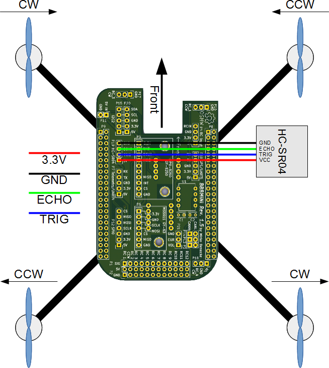
Rangefinder HC-SR04
Search for HC-SR04, there are a lot of sellers.
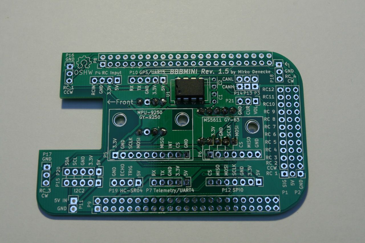
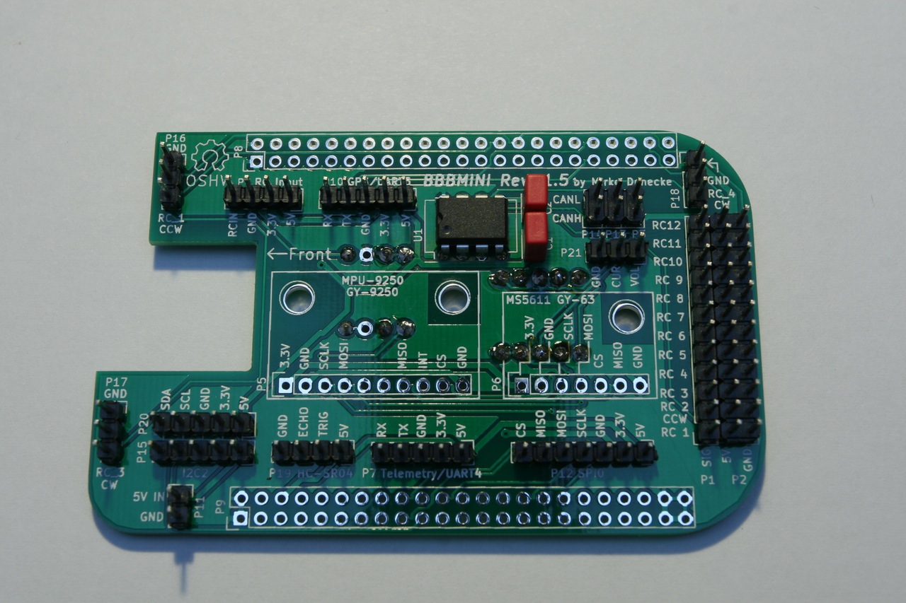
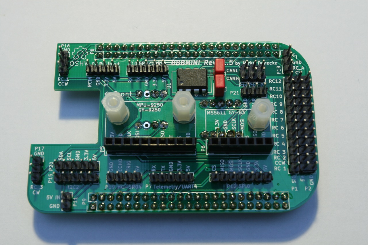
Connector
P1 & P2
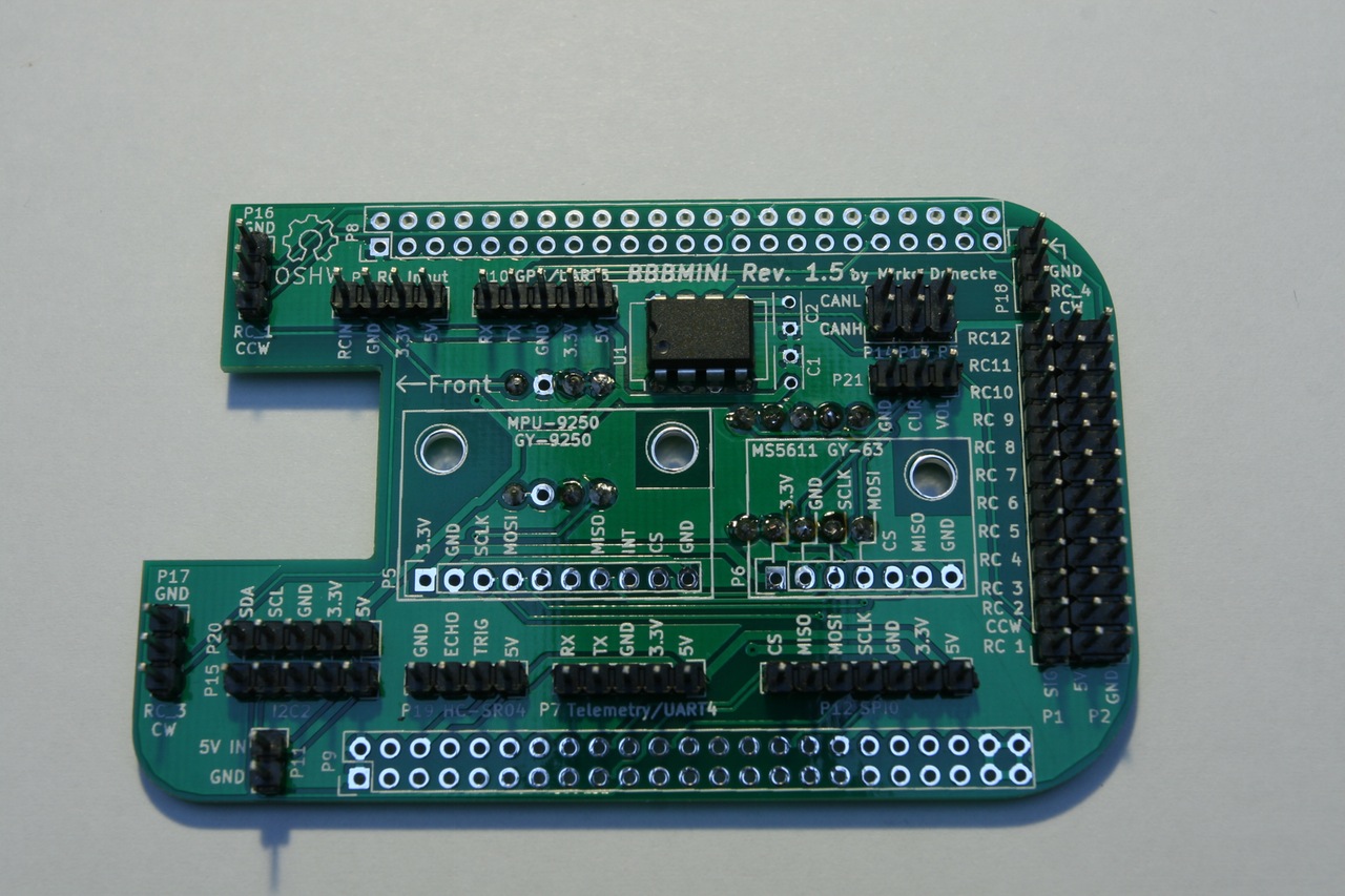
- 2.54mm pin header 3 x 12 straight or 90°
- 12 x RC out 3.3V
P3
- 2.54 mm pin header 1 x 2 straight
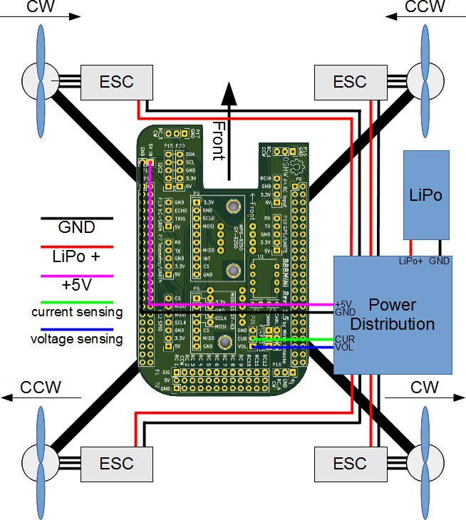
- Close this jumper to connect 5V BBBMINI power supply to P1 / P2 RC out 5V
P4
- 2.54 mm pin header 1 x 4 straight
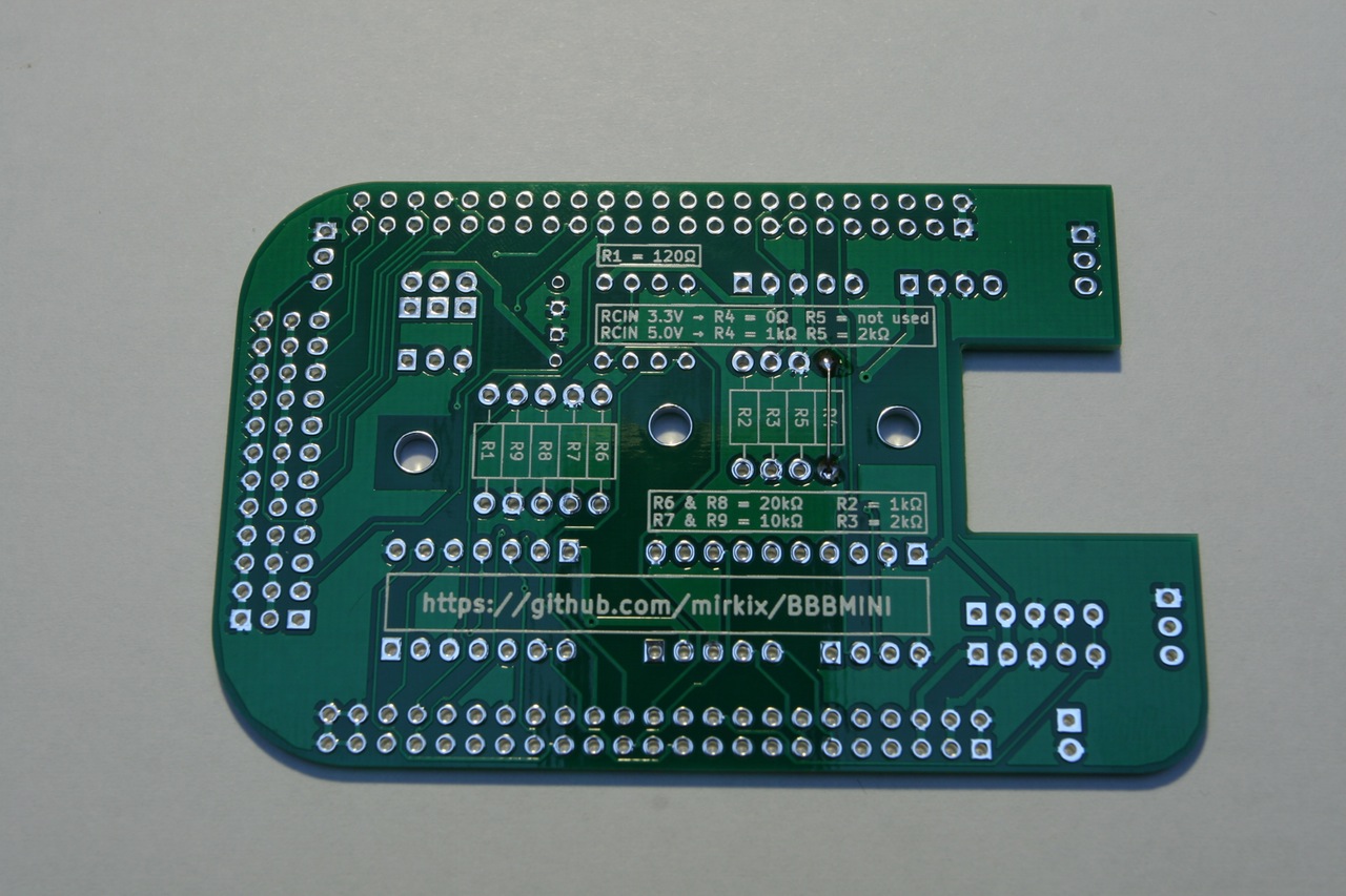
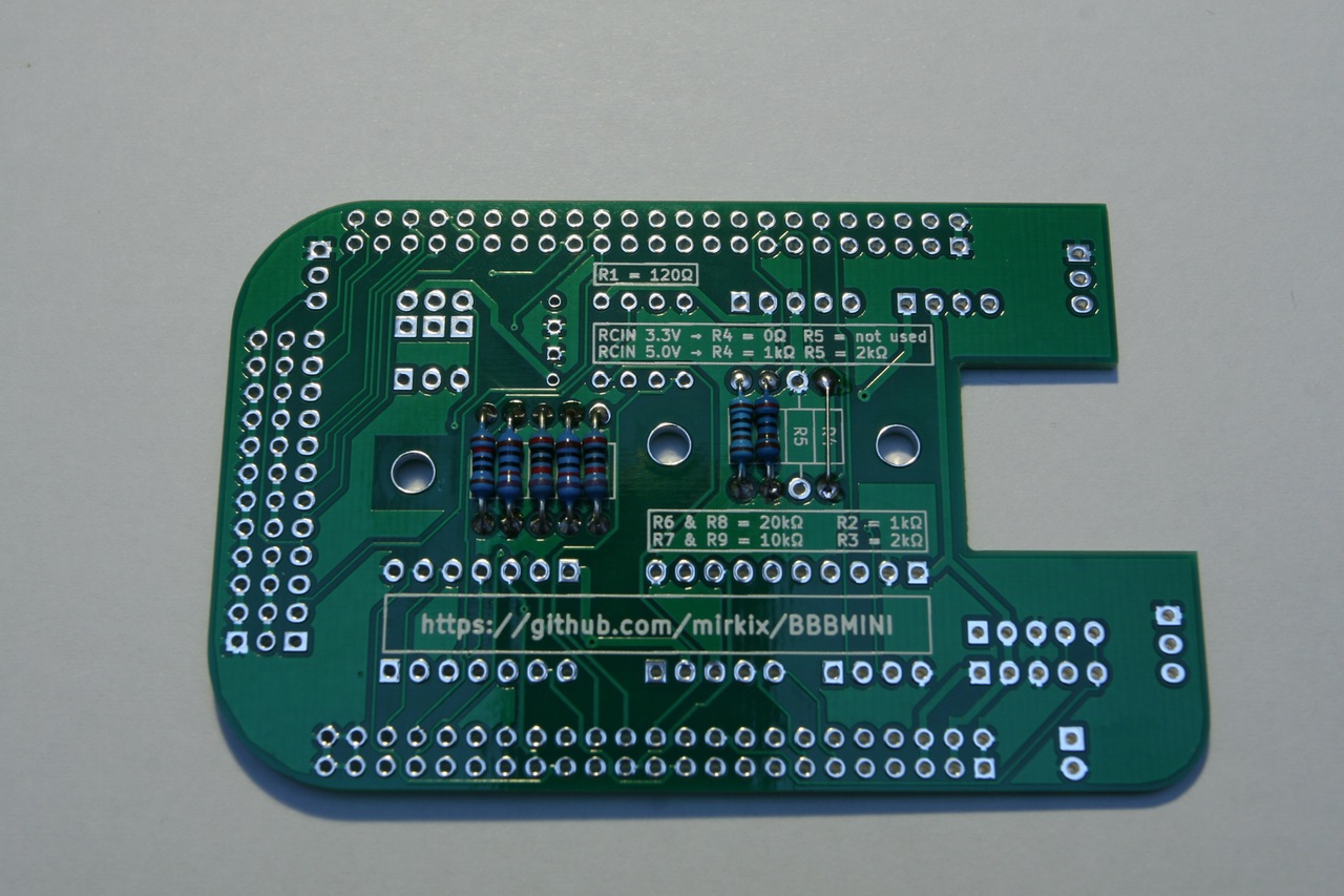
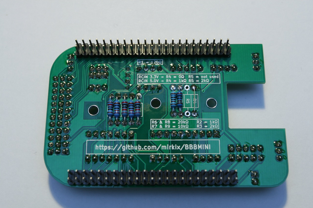
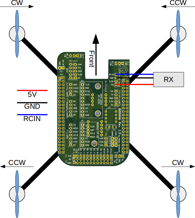
- RC receiver input.
- For 5V RCIN signal R4 = 1kOhm and R5 = 2kOhm.
- For 3.3V RCIN signal R4 = 0Ohm / bridged and R5 = open / not equipped.
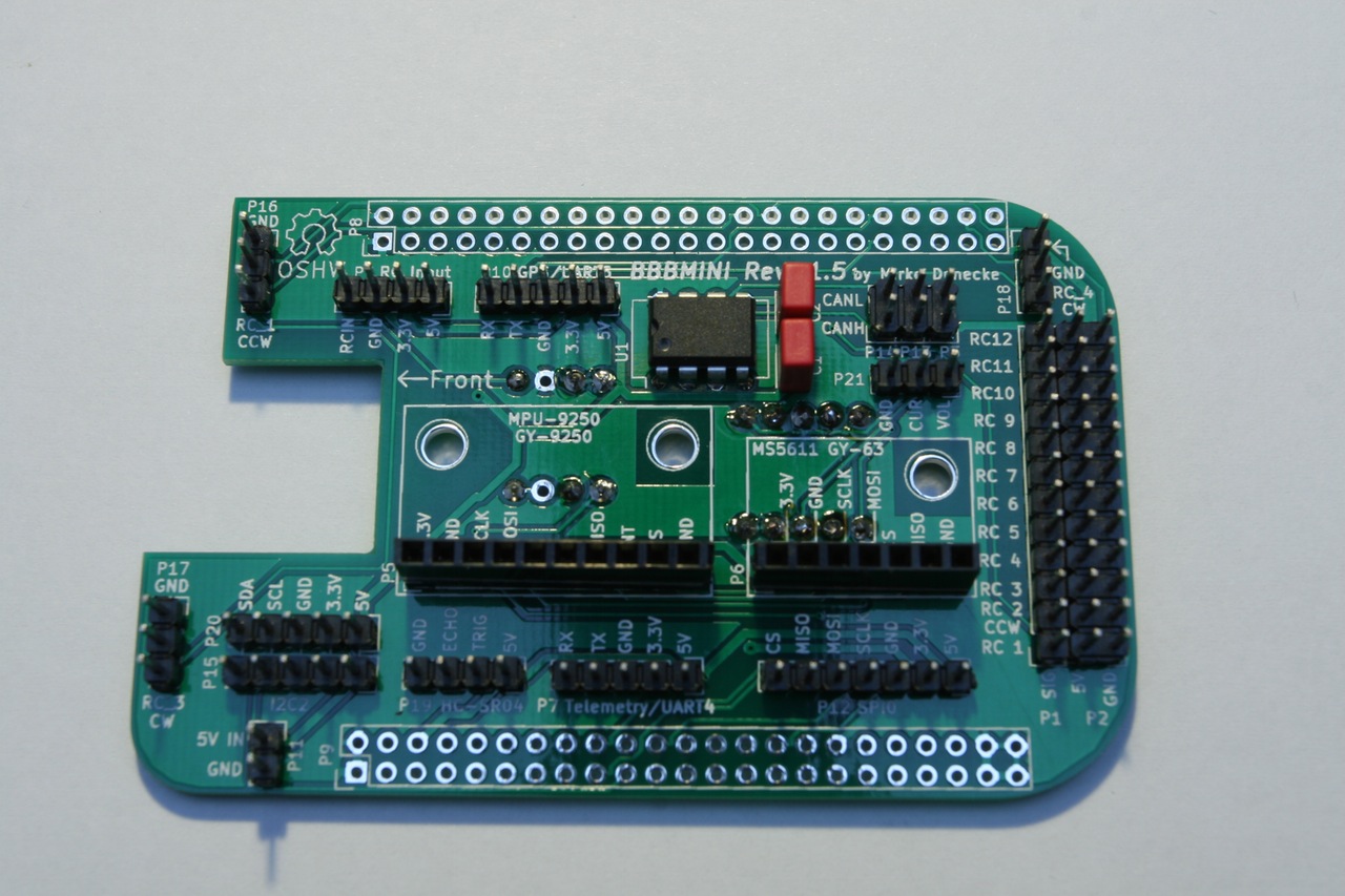
P5
- 2.54mm pin header female 1 x 10 straight
- MPU-9250 breakout board
P6
- 2.54mm pin header female 1 x 7 straight
- MS5611 breakout board
P7
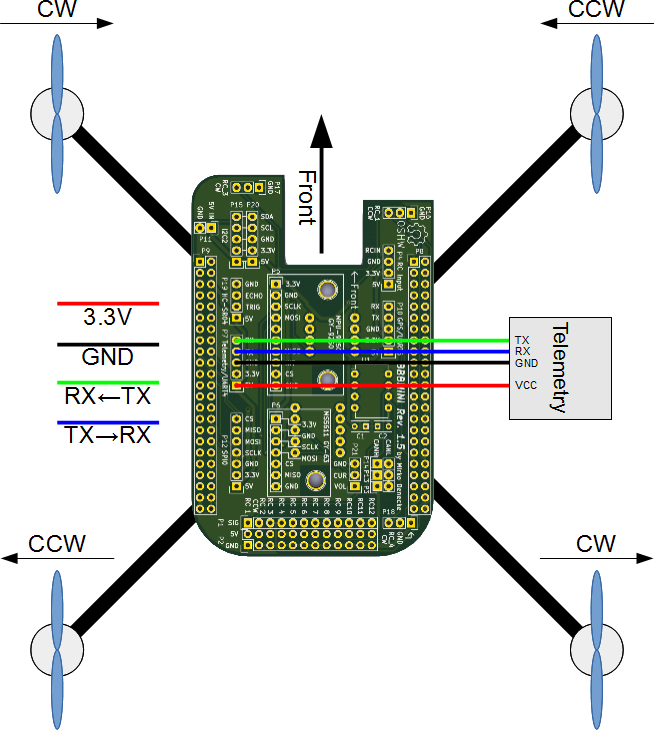
- 2.54mm pin header 1 x 5 straight
- UART4 port
- RX and TV 3.3V signals
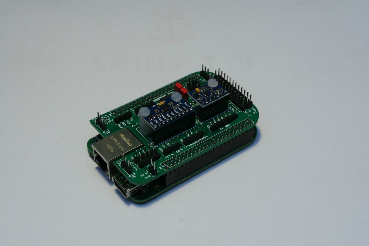
P8
- 2.54mm pin header 2 x 23 straight
- BeagleBone connector, pin header has to soldered on the back of the BBBMINI-PCB
P9
- 2.54mm pin header 2 x 23 straight
- BeagleBone connector, pin header has to soldered on the back of the BBBMINI-PCB
P10
- 2.54mm pin header 1 x 5 straight
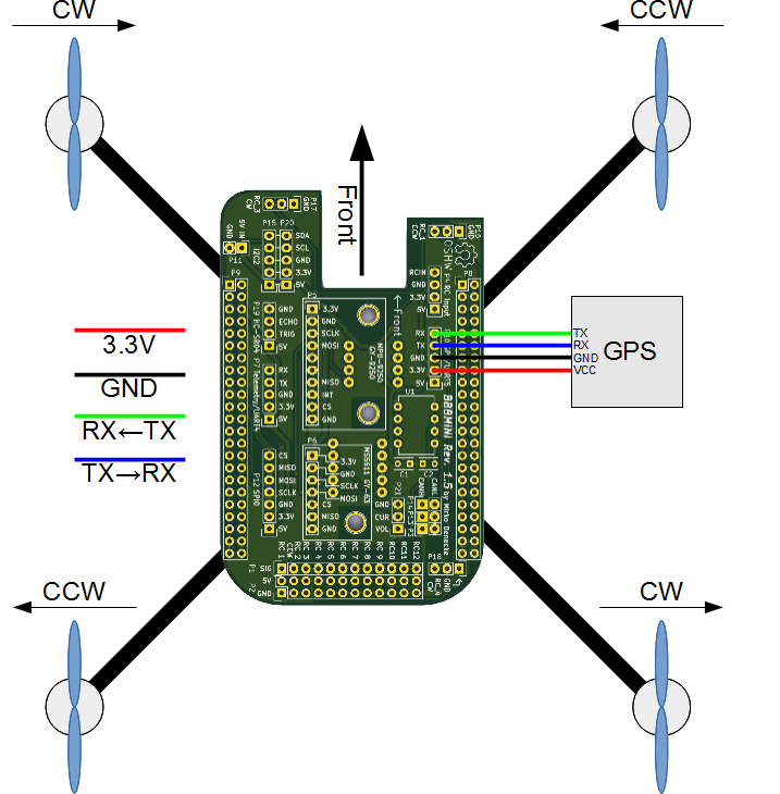
- UART5 port (GPS)
- RX and TX 3.3V signals
P11
- 2.54mm pin header 1 x 2 straight
- Connector for power supply. Use this connector to power the BeagleBone Black and BBBMIN-PCB. You can also use the BeagleBone Black power plug to power the BeagleBone Black and BBBMINI-PCB.
P12
- 2.54mm pin header 1 x 7 straight
- External SPI Bus connector for additional hardware.
- MOSI, MISO, SCLK and CS 3.3V
P13
- 2.54mm pin header 1 x 2 straight
- CAN Bus interface
P14
- 2.54mm pin header 1 x 2 straight
- Close this jumper to enable 120Ohm CAN Bus resistor.
P15
- 2.54mm pin header 1 x 5 straight
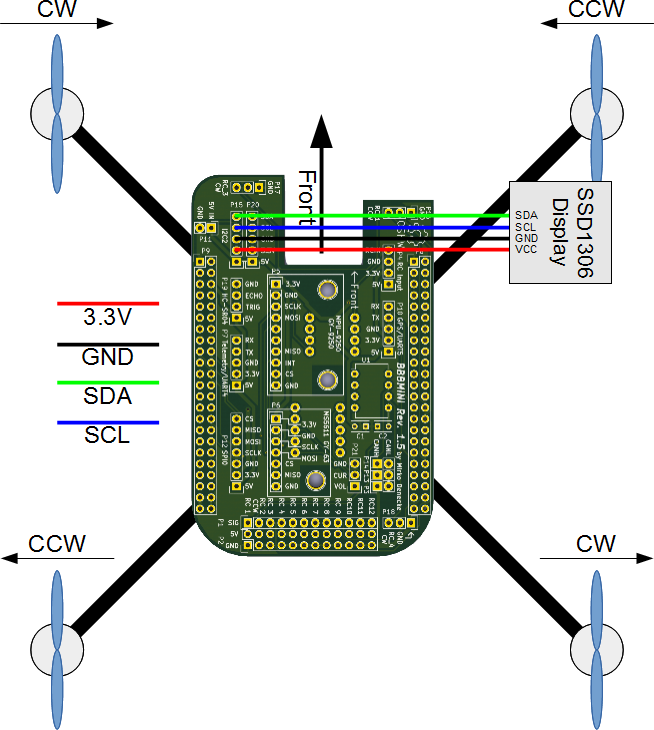
- External I2C Bus connector for additional hardware.
- SDA and SCL 3.3V
P16
- 2.54mm pin header 1 x 3 straight
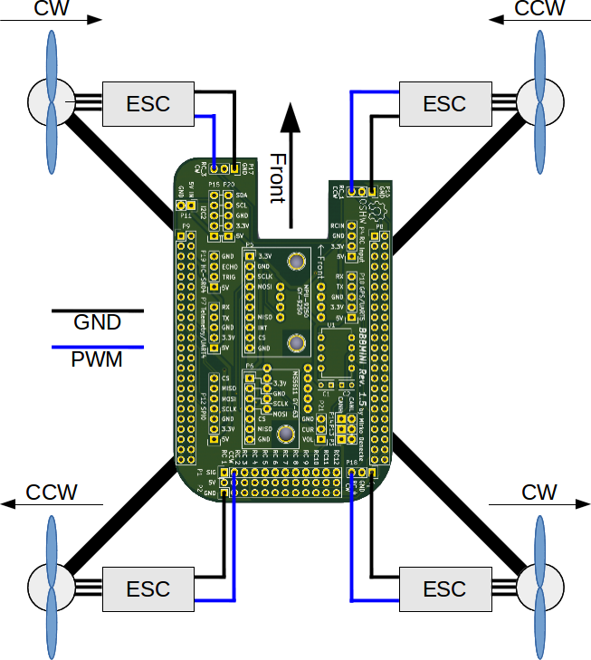
- Additional RC_1 ESC out connector for X-Quad configuration.
- RC_1 out 3.3V
P17
- 2.54mm pin header 1 x 3 straight
- Additional RC_3 ESC out connector for X-Quad configuration.
- RC_3 out 3.3V
P18
- 2.54mm pin header 1 x 3 straight
- Additional RC_4 ESC out connector for X-Quad configuration.
- RC_4 out 3.3V
P19
- 2.54mm pin header 1 x 4 straight
- Ultrasonic Range Finder connector
- Connect HC-SR04 Range Finder here.
P20
- 2.54mm pin header 1 x 5 straight
- External I2C Bus connector for additional hardware.
- SDA and SCL 3.3V
P21
- 2.54mm pin header 1 x 5 straight
- Current and voltage sensing via Power Module
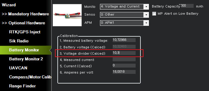
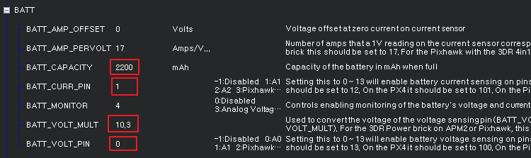
빨간 부분을 조정하여 Voltage를 맞춘다. (테스트 된 적절 값:10.3)