Pixhawk Autopilot
PIXHAWK is a high-performance autopilot-on-module suitable for fixed wing, multi rotors, helicopters, cars, boats and any other robotic platform that can move. It is targeted towards high-end research, amateur and industry needs and combines the functionality of the PX4FMU + PX4IO.
![]()
Key Features
- 168 MHz / 252 MIPS Cortex-M4F
- 14 PWM / Servo outputs (8 with failsafe and manual override, 6 auxiliary, high-power compatible)
- Abundant connectivity options for additional peripherals (UART, I2C, CAN)
- Integrated backup system for in-flight recovery and manual override with dedicated processor and stand-alone power supply (fixed-wing use)
- Backup system integrates mixing, providing consistent autopilot and manual override mixing modes (fixed wing use)
- Redundant power supply inputs and automatic failover
- External safety switch
- Multicolor LED main visual indicator
- High-power, multi-tone piezo audio indicator
- microSD card for high-rate logging over extended periods of time
Specifications

Processor
- 32bit STM32F427 Cortex M4 core with FPU
- 168 MHz
- 256 KB RAM
- 2 MB Flash
- 32 bit STM32F103 failsafe co-processor
Sensors
- ST Micro L3GD20H 16 bit gyroscope
- ST Micro LSM303D 14 bit accelerometer / magnetometer
- Invensense MPU 6000 3-axis accelerometer/gyroscope
- MEAS MS5611 barometer
Interfaces
- 5x UART (serial ports), one high-power capable, 2x with HW flow control
- 2x CAN (one with internal 3.3V transceiver, one on expansion connector)
- Spektrum DSM / DSM2 / DSM-X® Satellite compatible input
- Futaba S.BUS® compatible input and output
- PPM sum signal input
- RSSI (PWM or voltage) input
- I2C
- SPI
- 3.3 and 6.6V ADC inputs
- Internal microUSB port and external microUSB port extension
Power System and Protection
- Ideal diode controller with automatic failover
- Servo rail high-power (max. 10V) and high-current (10A+) ready
- All peripheral outputs over-current protected, all inputs ESD protected
Voltage Ratings
Pixhawk can be triple-redundant on the power supply if three power sources are supplied. The three rails are: Power module input, servo rail input, USB input.
Normal Operation Maximum Ratings
Under these conditions all power sources will be used in this order to power the system
- Power module input (4.1V to 5.7V)
- Servo rail input (4.1V to 5.7V) UP TO 10V FOR MANUAL OVERRIDE, BUT AUTOPILOT PART WILL BE UNPOWERED ABOVE 5.7V IF POWER MODULE INPUT IS NOT PRESENT
- USB power input (4.1V to 5.7V)
Absolute Maximum Ratings
Under these conditions the system will not draw any power (will not be operational), but will remain intact.
- Power module input (0V to 20V)
- Servo rail input (0V to 20V)
- USB power input (0V to 6V)
Schematics
- FMUv2 + IOv2 schematic – Schematic and layout
- How-to guide: Pixhawk with 6S batteries (> 4S) – An How-to guide to power PixHawk with >4S LIPO batteries
Pinouts
TELEM1, TELEM2 ports
| Pin | Signal | Volt |
|---|---|---|
| 1 (red) | VCC | +5V |
| 2 (blk) | TX (OUT) | +3.3V |
| 3 (blk) | RX (IN) | +3.3V |
| 4 (blk) | CTS (IN) | +3.3V |
| 5 (blk) | RTS (OUT) | +3.3V |
| 6 (blk) | GND | GND |
GPS port
| Pin | Signal | Volt |
|---|---|---|
| 1 (red) | VCC | +5V |
| 2 (blk) | TX (OUT) | +3.3V |
| 3 (blk) | RX (IN) | +3.3V |
| 4 (blk) | CAN2 TX | +3.3V |
| 5 (blk) | CAN2 RX | +3.3V |
| 6 (blk) | GND | GND |
SERIAL 4/5 port - due to space constraints two ports are on one connector.
| Pin | Signal | Volt |
|---|---|---|
| 1 (red) | VCC | +5V |
| 2 (blk) | TX (#4) | +3.3V |
| 3 (blk) | RX (#4) | +3.3V |
| 4 (blk) | TX (#5) | +3.3V |
| 5 (blk) | RX (#5) | +3.3V |
| 6 (blk) | GND | GND |
ADC 6.6V
| Pin | Signal | Volt |
|---|---|---|
| 1 (red) | VCC | +5V |
| 2 (blk) | ADC IN | up to +6.6V |
| 3 (blk) | GND | GND |
ADC 3.3V
| Pin | Signal | Volt |
|---|---|---|
| 1 (red) | VCC | +5V |
| 2 (blk) | ADC IN | up to +3.3V |
| 3 (blk) | GND | GND |
| 4 (blk) | ADC IN | up to +3.3V |
| 5 (blk) | GND | GND |
I2C
| Pin | Signal | Volt |
|---|---|---|
| 1 (red) | VCC | +5V |
| 2 (blk) | SCL | +3.3 (pullups) |
| 3 (blk) | SDA | +3.3 (pullups) |
| 4 (blk) | GND | GND |
CAN
| Pin | Signal | Volt |
|---|---|---|
| 1 (red) | VCC | +5V |
| 2 (blk) | CAN_H | +12V |
| 3 (blk) | CAN_L | +12V |
| 4 (blk) | GND | GND |
SPI
| Pin | Signal | Volt |
|---|---|---|
| 1 (red) | VCC | +5V |
| 2 (blk) | SPI_EXT_SCK | +3.3 |
| 3 (blk) | SPI_EXT_MISO | +3.3 |
| 4 (blk) | SPI_EXT_MOSI | +3.3 |
| 5 (blk) | !SPI_EXT_NSS | +3.3 |
| 6 (blk) | GPIO_EXT | +3.3 |
| 7 (blk) | GND | GND |
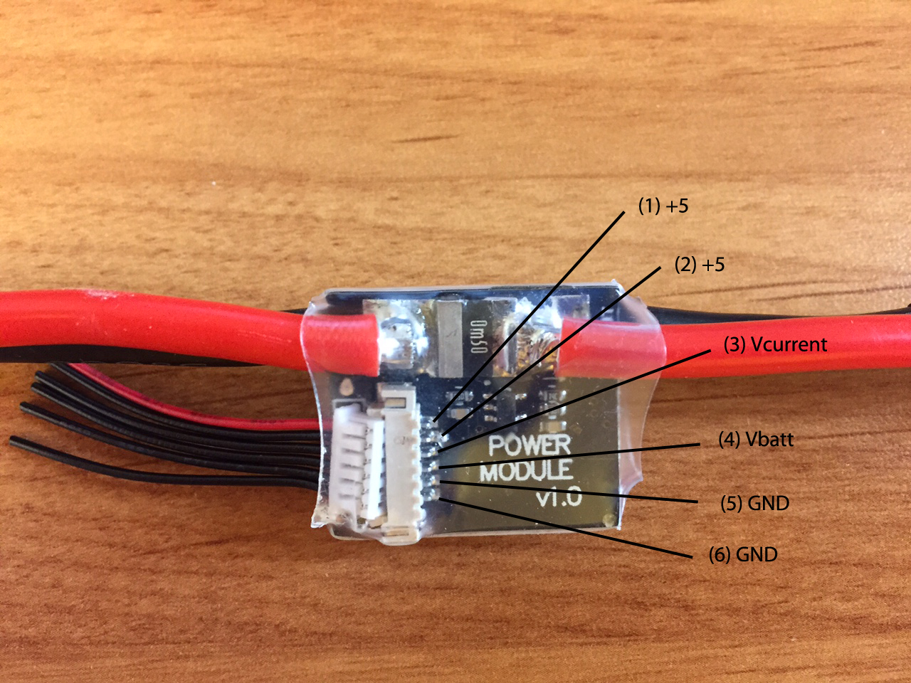
POWER
| Pin | Signal | Volt |
|---|---|---|
| 1 (red) | VCC | +5V |
| 2 (blk) | VCC | +5V |
| 3 (blk) | CURRENT | +3.3V |
| 4 (blk) | VOLTAGE | +3.3V |
| 5 (blk) | GND | GND |
| 6 (blk) | GND | GND |
SWITCH
| Pin | Signal | Volt |
|---|---|---|
| 1 (red) | VCC | +3.3V |
| 2 (blk) | !IO_LED_SAFETY | GND |
| 3 (blk) | SAFETY | GND |
Console Port
The system's serial console runs on the port labeled SERIAL4/5. The pinout is standard serial pinout, to connect to a standard FTDI cable (3.3V, but its 5V tolerant).
Please refer to the NSH Serial Console Wiring page for details how to wire up this port.
Parts / Housings
- ARM MINI JTAG (J6, not populated per default): 1.27 mm 10pos header (SHROUDED, for Black Magic Probe: FCI 20021521-00010D4LF (Distrelec, Digi-Key) or Samtec FTSH-105-01-F-DV-K (untested) or Harwin M50-3600542 (Digikey or Mouser)
- JTAG Adapter Option #1: BlackMagic Probe, comes without cables, needs the Samtec FFSD-05-D-06.00-01-N cable (Samtec sample service or Digi-Key Link: SAM8218-ND) or Tag Connect Ribbon and a Mini-USB cable
- JTAG Adapter Option #2: Digi-Key Link: ST-LINK/V2 / ST USER MANUAL, needs an ARM Mini JTAG to 20pos adapter: Digi-Key Link: 726-1193-ND
- JTAG Adapter Option #3: SparkFun Link: Olimex ARM-TINY or any other OpenOCD-compatible ARM Cortex JTAG adapter, needs an ARM Mini JTAG to 20pos adapter: Digi-Key Link: 726-1193-ND
- USARTs: Hirose DF13 6 pos (Digi-Key Link: DF13A-6P-1.25H(20))
- Mates: Hirose DF13 6 pos housing (Digi-Key Link: Hirose DF13-6S-1.25C)
- I2C and CAN: Hirose DF13 4 pos (Digi-Key Link: DF13A-4P-1.25H(20))
- Mates: Hirose DF13 4 pos housing (Digi-Key Link: Hirose DF13-4S-1.25C)
- USB (J5): Micro USB-B
- Mates: Cell phone data / charger cables, e.g. Digi-Key Link: ASSMANN AK67421-0.5-R
Peripherals
Supported Platforms / Airframes
Any multicopter / airplane / rover or boat that can be controlled with normal RC servos or Futaba S-Bus servos. More details are available on the platforms page.